@joie if you want to displace a vertex along its normal, you need to scale the normal vector of that vertex by the offset amount and then add that to the vertex position. I did a PG for a different question that dealt with this specific method but in that one I am using the vertex color to isolate the vertices that displace. You can ignore that part of the graph, and just reference the scaling of mesh.normal by your displacement amount, wherever that comes from (texture or factor).
Hi there @PatrickRyan and thank you very much for that graph.
I’ve tried to implement the vertex normal thing into mine, but new things arise LOL.
Now the vertex, when the multiplier is zero, they go to world zero coordinates. But they should NOT move at all. So when the multiplier is zero, they don’t move and then they need to move in the normal direction the amount set in the multiplier, hope that makes sense.
And I need the vertex go in the normal direction ONLY. I guess that means I need only the Y axis (meaning Y axis = normal direction) and not the X and Z.
You can see my stupid attempt here.
I say stupid because this NME is so complex for doing things like this.
Thanks!
Hi there @PatrickRyan, I don’t know if you may be on vacation, so bear that in mind. Any information or help on this issue would be very appreciated since I am completely lost on what I’m doing wrong.
Thanks in advance
@joie, sorry for the delay in response. We need to explore turning a height map into a normal map in NME as the nodes we have right now fall a little short for a high-quality conversion. This work is underway, but I don’t have an estimate on when they will be available.
What I did for now is use a derivative to convert height to normal since we need to recalculate the surface normals after vertex displacement. This method is cheap because the GPU already needs to use this calculation so it’s already available, but the problem is that it isn’t very smooth. You will see a lot of pixeled artifacts in the normal based on zoom level. But this may unblock you for now while we finish up the other nodes and a new method for converting height to normal.
I did frame up the node graph under function so you could read it a little better and understand what’s happening in each section. Let me know if you have questions.
Hi there Patrick, I hope you had fun on your vacations!
Thank you very much for the graph, I’ll digo into it in a few days when I can free some time for it.
I thought this was MUCH simple to achieve, because I’m not tesellating any mesh, I’m just moving the vertices already present in it. But that comes from my offline rendering mind, where all those calculations are made by default LOL
I’ll tell you bak in few days.
Thanks!
Hi there again @PatrickRyan
I tried to do my best to copy your graph, you can find it here.
There is one more thing I wanted to address.
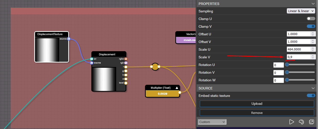
I need to make the displacement only visible in a certain range of the UV space. It should be as simple as telling the image source node to have the vScale of the texture to 0.9 (not the 1.0 default). But for some reason it doesn’t do anything.
Could you, please, check that?
If I read your question correctly, you want to control where in UV space that you are displacing your mesh. You would do that with some conditionals that you can control via variables to set min/max values. I updated your graph with the bit in the middle with a few conditionals. Not sure if this is what you mean, but it should give you some ideas if I read the question wrong.
Also I wanted to point out that your shader isn’t physically accurate as there is no such material that is 50% metallic. The only time you will see gray in a metallic map is when you have a substance caked on metal and it’s only the aliased transition that would be not 0 or 1 in a metallic map. This has to do with the fact that we are contributing base color into the reflections of metallic surfaces and having a value of 0.5 blends both base color and specular color in reflections which isn’t accurate. If you have a piece of metal that has mud on it for example, you will see a noise spattering of black on the white map and some anti-aliasing around the black pixels, which would be physically accurate, but large areas of a value other than 0 or 1 in metallic does not physically exist.
About the physically plausible material, I know all that. I was using a 0.5 for metallic just for lookDev reasons, because in the preview there is no reflection environment to reflect in the PBR material, so a full metallic one looks almost black. But the belt is rubber like, so nothing of that really matters, but thanks for point me to that.
About the material itself, thanks so much for it, I just needed to change U for V in order to limit the range I need, and that’s it.
Finally I have some discrepancies between my model UVs and the converted GLB I use for preview (I didn’t do the conversion though), and looks like the UVs on both objects are not the same. But NME doesn’t have a UV editor or viewer to check that, so I don’t know.
In order to make NME more artist friendly, is there any place to make suggestions for it?
Cheers.
Starting a new thread on the forum is the best place to discuss new feature requests. This way the community and team can have a discussion about feasibility, future plans, and where we spend our resources, including solicitations for community contributions.
I managed to get everything as I wanted with the shader (found here).
There is just one more thing that annoys me and it’s the shading itself.
Since we are displacement some vertex, then we have to recalculate the normals of the surface.
That part of the shader is made in this frame:
The flat top part should have almost no difference in shading, but they have two different colors:
Since the normal recalculation part of the graph is just a copy of the one you made (if I remember correctly), I don’t know what the hell is going on there, and in fact I don’t understand anything. So I can’t fix that shading artifact.
@joie, so I can accurately respond to the question, is there any way you can share the latest version of your belt mesh as a .glb? Part of the answer may lie in the construction of the mesh so I want to make sure I am testing out the file the shader is intended for. Even a link in a private message would be helpful if you can’t post it publicly. Thanks for your help!