UVs for ExtrudedPolygons?

I’m having trouble wrapping my head around what causes a particular UV to tiled in a given way.
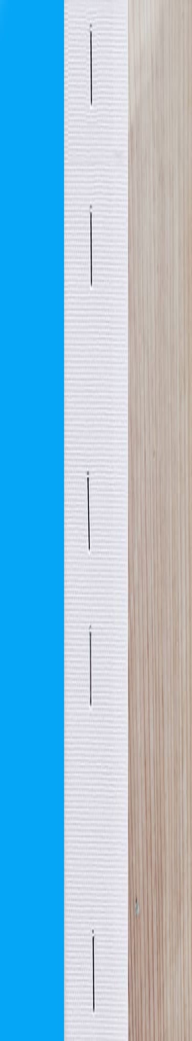
I’m trying to wrap this texture (https://cp-development.s3.amazonaws.com/wood-staples-3.jpg) around the frame here such that the outside edge is blue, the back side is white with some staples, and the inside edge is wood textured. https://www.babylonjs-playground.com/#2CU0P1#52

In particular here are the UV definitions and the coordinates as I understand them – but i can only get two of the faces to show up in the model? The wood texture never seems to get applied correctly.

var faceUV = new Array(4);
    faceUV[0] = new BABYLON.Vector4(0.3, 0, 0.6, 1); // front (should be staples) 
    faceUV[1] = new BABYLON.Vector4(0, 0, 0.3, 1); //  maybe outside? (shows up inside AND outside edge?) -- blue
    faceUV[2] = new BABYLON.Vector4(0.6, 0, 1, 1); // maybe hidden front?
    faceUV[3] = new BABYLON.Vector4(0.6, 0, 1, 1); //  maybe inside edge? - 

I do not think you can as the provided UVs will be the same for each “sides” of the extruded face hence the blue inside and outside. You can only control top, sides and bottom UVs in an array of 3 Vector4.

In your case creating the model either programmatically or in art tool would be preferrable.

Adding @JohnK who is a maths GURU for those kind of issues as I ll happily learn from the answer

UPDATE
I posted a PG that I thought was using the extrude method, but it looks like it was actually building the mesh data from scratch. My bad.

*Original Post

this might be to complex to extrapolate the information out of, but I’m pretty sure I do what you are looking to do in this demo.

1 Like

ExtrudePolygon only allows three faceUVs, top, bottom and edge so you cannot texture an outside and inside edge differently.

To do what you wish requires a custom mesh with 4 faceUVs used in its creation.

If I get chance I will have a go at setting one up.

1 Like

Riiiight, that’s sort of what I was thinking might have been the case, but didn’t quite understand why the ExtrudePolygon would be limited to only 3 faceUVs. I’ll dig around in Pryme8’s example and see if I can extrapolate it, but if you happen to get a chance at setting one up, that would be very much appreciated.

Let’s give it a go. First a bit of planning

Let’s extend to a more general case with a sloping profile, Profile 1as well as a box profile, Profile 2. For either profile base, inner and outer heights will form the parameters along with the picture size. For Profile 1 and some occassions Profile 2 the pricture will sit in the inner edges, As in your case the picture may sit fitting the outer edges.

When fitToInner = true the outer length will be determined by the inner length and vece versa.

The origin for the vertices will sit at the center of a box of height inner height.

vertices 0, 1, 2, 3 inner edge, 3, 2, 7, 6 top, 4, 5, 6, 7 outer edge, 0, 1, 4, 5 base, numbers have to be increased to form seperate planes to apply uvs and colors.

Let’s have face uvs and colors 0 inner edge, 1, top, 2, outer edge, 3 base.

Ufortunately the code I use for ‘createFrameSection’ messes with the angles and positions and names you used. Each frame section is built with the base (back of frame) lying on the xz plane.

Hopefully there is enough there for you to sort things out.

Will have another look at the faceUV and colors as not sure they are set quite right.

EDIT Generally faceuvs are OK but depending on ratio in image they will get stretched and distorted across the mitred edges

2 Likes

The polygon to extrude can have unknown multiple sides hence top, bottom and multiple edges with multiple faceUVs and colors for each to be dealt with individually. Easiest to deal with as top, bottom and continuous edge, hence three faceUVs and colors.

I got the inside edge working with these changes, but the outside edge faceUVs now seem… i want to say inverted? https://www.babylonjs-playground.com/#2CU0P1#56

The way I constructed the frame it might be better to have your texture running in horizontal rather than vertical strips.

Change to horizontal strips

Also note that when using uvs bottom left of image is (0, 0) and top right (1, 1), ie v is measured vertically UPWARDS. Not as in the image in your first post.

1 Like