Seeking feedback on Havok Physics visualizations for debug

I’m seeking feedback on my approach to physics debugging visualization.

The ideas and development were spurred by @regna post here and the contributions in that thread by @roland, @Cedric, @riven04, and @qq2315137135.

All the details are below. To set the stage, here is how you enable the visualization of lines emanating from a contact point in the direction of its normal and scaled relative to the size of the impulse imparted. All observers, data management, and the translation of the PhysicsEvent data into a visualization every frame are handled within the class.

var debugLines = new ContactLines({width:0.005,propertyName:"impulse",scale:2e6},hk,scene).enable();

And to turn the visualization and data collection off:

debugLines.disable();

Please review the following and feel free to provide feedback about any aspect. I am already planning to translate it into TypeScript to improve the likelihood of it becoming integrated and distributed with Babylon.

I have a set of classes that enable easy visualizion of Havok physics. I’m looking for feedback on this initial approach. After a brief review of a few engines and their associated mechanisms for visualization, it appears that PhysicsDebug layers from other engines separate out 1) the collection of the data (which come from the engine itself) and 2) a defined interface for visualization or transmission of that data. An object/instance of a visualization class implements that defined interface that is attached to and called directly from the engine. The physics engines vary in the level of integration with the visualization class, thus the visualization interface varies.

My approach here attaches to Havok (by passing in the Plugin) and extracts data either from Havok Plugin methods (havokPlugin) or directly from the Engine (havokPlugin._hknp). The Havok Plugin is a thin layer above the Havok engine itself. Some of the methods in the engine can be quite complicated, such as when body instances or compound shapes are involved. I’m leaning towards adapting to the Plugin instead of the Engine because it reduces this complexity. And because user-level Babylon code only uses the Plugin, any differences between the Engine and the Plugin still constitute a “problem with Babylon Havok,” so there is little to be gained by extracting data “closer to Havok.” When the information needed is only available from the Engine or when there are performance improvements from avoiding additional memory or translation, the Engine is accessed directly.

// Examples of Plugin methods used:
//havokPlugin._bodies
//havokPlugin.onCollisionObservable

// Examples of Havok engine methods used:
//havokPlugin._hknp.HP_Body_GetQTransform
//havokPlugin._hknp.HP_Body_GetActivationState

Below, you’ll find an explanation of my approach including what is already implemented and ideas for additional visualizations and options. Please comment!

/**
 * 
 * Currently, the general pattern is shown below. Examples are shown at the end.
 *  
 * class PhysicsDebug* { // for example: ContactLines, ContactPoints, DebugMeshes
 * constructor(options, havokPlugin, scene) - allocate empty arrays, capture options
 *     options - {parameter:value,...}
 * enable() - allocate memory and enable observers for rendering and object management
 * disable() - deallocate memory to minimal and disable observers
 *    - memory allocated is similar to post-constructor
 * set parameter(value) - change parameter value
 *    .
 *    .
 *    .
 * }
 * 
 * DebugMeshes contains options to show physics parameters related to PhysicsBody
 * and in the local space of the PhysicsBody:
 * - wireframe of PhysicsBody shape
 * - ActivationState ACTIVE or INACTIVE (color)
 * - can add? CG, inertia vector, local axes, bounding box
 * - maybe: face normals
 * - what about? ActivationControl, PreStepType, MotionType (with duration)
 * - what about? SimpleMaterial option along with wireframe? 
 * - what about? velocity angular/linear, possibly scaled relative to maximums?
 * - what about? adding/removing per body? specifying inclusion or exclusion lists?
 * 
 * ContactPoints shows the points of collision or trigger (with duration)
 * - currently a sphere with specified diameter
 * - what about? color based on EventType? attached to one or both Meshes with duration?
 * 
 * ContactLines shows lines at contact points in the direction of its normal.
 * - width parameter
 * - scaled by impulse (collision only) or distance (collision or trigger)
 * - additional scale parameter
 * - color by eventType: Collision / Trigger, Start / Continue / Stop
 * - what about? adding duration?
 * - what about maybe? highlight facet on mesh (with duration)?
 * 
 * Constraints (not yet started)
 * - with limits?
 * - what about? motors and spring-dampened motors
 * Types: BALL_AND_SOCKET, DISTANCE, HINGE, LOCK, PRISMATIC, SIX_DOF, SLIDER
 * 
 * No idea yet on how to handle these, but here is a list of general constraint parameters.
 * 
 * PhysicsConstraintParameters {
 *     axisA?: Vector3;
 *     axisB?: Vector3;
 *     collision?: boolean;
 *     maxDistance?: number;
 *     perpAxisA?: Vector3;
 *     perpAxisB?: Vector3;
 *     pivotA?: Vector3;
 *     pivotB?: Vector3;
 * }
 * 
 * Example usage:
 * new ContactLines({width:0.005,propertyName:"impulse",scale:2e6},hk,scene).enable();
 * new ContactPoints({duration:1000,diameter:0.01},hk,scene).enable();
 * new DebugMeshes(hk,scene).enable();
 */
5 Likes

I would add that physics visualization/debug vis is the first step toward a physics editor.
Constraints are a bit difficult to set in the code. The possibility to edit/tweak contraints and live test it would be so great!

2 Likes

Thank you so much, @HiGreg :slight_smile: I love the list of features you shared.

I’ve been trying to debug visualize Havok joint limits, and I think I found a bug:

It would be amazing if we had full debug visualization of Havok joints.

Agreed. I think 6DOF is a superset of all others. I’m ruminating on how to do it while I’m learning how to visualize data from Havok. As you might imagine, and can see in the playground below, it’s not trivial.

To show how simple it is to use the classes I’m creating (instantiate the class with options, and call .enable()), I’ve added my current working DebugMeshes class to a playground to show how it works.

I’ve added a few options since my last post. The playground mostly just shows off local axes and linear velocity.

DebugMeshes contains options to show physics parameters related to PhysicsBody in the local space of the PhysicsBody:

  • wireframe of PhysicsBody shape
  • ActivationState ACTIVE or INACTIVE (color)
  • Center of Mass,
  • local axes,
  • bounding box,
  • linear velocity

Comments welcome! If you try it out with other playgrounds, add a link here. Be sure to copy the whole class including the version date.

I’m thinking of changing the name from Meshes to Bodies or similar.

The playground is one that reveals either a bug or limitation in Havok Engine (for more info about the playground, see Havok Precision - #33 by HiGreg)

Edit: running for a minute or two, the playground crashes with the upper left sad face box. Rerunning gives the error “Unable to create uniform buffer.” Not sure if there’s a general problem or if I’m just stressing my browser.

2 Likes

And here’s a video of bouncy dice with contact points, axes, and linear velocity. Near the end you can see inactive physicbodies turn from green to red.

2 Likes

That’s awesome! Were the red and green colors of the dice based on the ActivationState?

Yes. Each frame on each body, I call HP_Body_GetActivationState() directly from the Engine. I don’t see the equivalent in the Plugin.

1 Like

Here’s an update on the physics debug visualization classes. I’ve converted to TypeScript, and toiled through quite a few errors. I’ve gone all-in on GreasedLineMesh, but not sure about the amount of perFrame updates on all the velocity and contact lines. Something was causing the WebGL context to be lost.

Although context loss seems to be gone at the moment, there are still weird freezes when there are lots of moving objects (about 3 seconds of smooth followed by 6 seconds of freeze, repeating). I’m testing with about 56 bouncing dice in a box. Here’s a preview with just a few.

  • DebugBodies - wireframe or boundingbox, active (green) inactive (red), center of mass, local axes, velocity linear

  • ContactLines - shows collision lines along the normal, scalable by impulse. Color indicates starting (red) or continuing (yellow).

  • ContactPoints - shows temporary dots (lasting 250 milliseconds) at contact points

       /* Example usage:
       * new ContactLines({width:0.005,propertyName:"impulse",scale:2e6},hk,scene).enable();
       * new ContactPoints({duration:1000,diameter:0.01},hk,scene).enable();
       * new DebugBodies({}, hk, scene).enable();
       *
       */
      
      // example:
      // new DebugBodies({showAxes:true,velocityScale:.2,velocityLineWidth:0.01,},hk,scene).enable();
    
3 Likes

First draft of joints visualization.

This is a generic implementation that visualizes pivot point and axis of PhysicsConstraint.

No limits and no 6DOF yet.

Somewhat optimized for updating transforms from PhysicsBody as each constraint is a Mesh with submeshes (i.e. Merged), then thinInstanced for each joint.

Only showing one constraint, both A and B (aka parent and child). Hopefully this will continue to work well as I add constraints and joints.

3 Likes

That’s awesome :smile: If it can help, I can take a video of built-in debug drawings for different joint types in Bullet and PhysX. We could use good aspects from both in the Havok joint debug drawing

That would help immensely!

Also helpful would be code or playgrounds implementing Havok joints and constraints.

1 Like

Awesome! Let me look into the video and PG’s later today and the weekend

1 Like

I haven’t built this into a debug class, but here’s what I’ve got so far. Almost posted as another thread but don’t want to pollute.

Visualizing constraints’ linear axes.

First, the cool visualization. After loading, tap for chaos.

Looking for feedback on this theory. I haven’t seen it presented this way, but I can’t say I’ve read all the documentation. Regarding the AxisMode of PhysicsConstraints, is there anything wrong with this way of thinking about it?


There are three vectors and one point that are user-specified on each of two bodies in a PhysicsConstraint. These axes are called Axis, perpAxis, and the (unnamed) normal to Axis and perpAxis. These form three orthogonal axes with their origin at the user-defined point called Pivot. One body is called A, or Parent, and the other is called B, or Child.

Each of these axes has a LINEAR component and an ANGULAR component, where LINEAR references position along the axis and ANGULAR references rotation around that axis. In this context, X, Y, and Z are references to Axis, PerpAxis, and the Normal, respectively.

A user can place fixed upper and lower limits on each of these axes. These limits constitute a box relative to box A’s axes within which body B’s Pivot is constrained.

Here is a visualization of this. In the playground, boxA is red and boxB is yellow. BoxB’s Pivot is purple and the linear constraints are visualized as a gray box. Gravity is set to zero and each body has the same mass. Tapping the screen imparts a force to boxB. Note how the purple Pivot says within the gray limits. When the yellow box reaches its limits, momentum is transferred to boxA (through the constraint) and boxA moves as a result.

All possible constraint combinations (see this post) are shown. This is the same demo as the first link, but with non-cube limits:

If you modify the code to attach the limits box to boxB instead of A, then it’s not seeming to constrain boxA. I think this substantiates the theory above.

3 Likes

edit for words

If my theory above is correct on the linear limits essentially being a box containing boxB pivot, then editing seems straightforward with a gizmo. I haven’t yet played at all with gizmos yet.

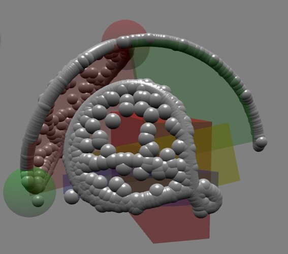
I haven’t worked out the exact positioning of the elements for showing angular limits, but here’s a rough (and incorrect) draft of what I’m working on for the angular limits. If my working theory is correct, I can add axis balls fixed in boxB local space, then add rotational disks centered on pivotB yet having the rotation of boxA’s axis/perp/normal in world space. Each of the three axis balls are contained in their respective rotational disk. My thought is to show the disk and ball depending on the axis’ ANGULAR mode.

  • LIMITED - show a disk as arc that contains the ball. The arc ends/edges are located at the limits.
  • LOCKED - narrow disk arc “pointing” to the associated ball, visualizing that the ball is “locked in place”
  • FREE - no disk, no ball

The big balls and white arc in the center of the playground below are me just working out angles and rotations.

Some of the constraints have a blue, red, and/or green disk that represent the ANGULAR freedom of movement. These disks are incorrectly placed/rotated , but show the idea.

Comments welcome as I continue to develop the concept and fix the code.

I’m not sure how yet, but I think I could enable the toggling of each axis’ mode (FREE/LOCKED/LIMITED) and enable the modification of the disks edges and/or the disks’ rotation. I think that constitutes the full editing of ANGULAR degrees of freedom?

Combined with similar toggling on the LINEAR degrees of freedom as well as editing the “LINEAR box” described above (i.e. the boxes shown in the playground), then we have full editing of constraints?

2 Likes

@HiGreg I recorded a video of joint limit debug visualizations for Bullet and PhysX. Thank you for your patience here :slight_smile:


Joint Limit Debug Visualization: Bullet vs. PhysX vs. Havok (Custom)

I tried incorporating some parts from Bullet and PhysX into debug visualizations for Havok, though haven’t yet figured out how to draw a pyramid nicely


Code Snippet

It’s hard to move all the Havok code from the video to a PG. In the meantime, I’ve pasted the joint limit debug visualization part below:

Havok Joint Limit Debug Visualization Code
#collectConstraints(): void {
	const fn = functionName(this.#collectConstraints);

	const {
		// vector3A-B used by setBabylonMatrixFromTransform()
		vector3C: parentFramePositionBB,
		vector3D: rotatedParentFramePositionBB,
		vector3E: childFramePositionBB,
		vector3F: rotatedChildFramePositionBB,
		vector3G: fromLocalPositionBB,
		vector3H: fromWorldPositionBB,
		vector3I: toLocalPositionBB,
		vector3J: toWorldPositionBB,

		// quaternionA used by setBabylonMatrixFromTransform()
		quaternionB: parentBodyRotationBB,
		quaternionC: childBodyRotationBB,
		quaternionD: parentFrameRotationBB,
		quaternionE: childFrameRotationBB,

		matrixA: parentBodyWorldMatrixBB,
		matrixB: childBodyWorldMatrixBB,
		matrixC: parentFrameWorldMatrixBB,
		matrixD: childFrameWorldMatrixBB,
		matrixE: parentWorldMatrixBB,
		matrixF: childWorldMatrixBB,
		matrixG: parentFrameRotationMatrixBB,
		matrixH: childFrameRotationMatrixBB,
	} = BABYLON_SHARED_DATA;

	for (const constraint of this.#constraintMap.values()) {
		// if (!constraint.inWorld) {
		// 	continue;
		// }

		const id = constraint.vendorConstraint;

		const {
			parentBody,
			childBody,

			parentFrame,
			childFrame,
		} = constraint;

		const [parentPosition, parentRotation] = parentBody.getTransform();
		const [childPosition, childRotation] = childBody.getTransform();

		setBabylonQuaternion(parentRotation, parentBodyRotationBB);
		setBabylonQuaternion(childRotation, childBodyRotationBB);

		setBabylonMatrixFromTransform(
			{
				position: parentPosition,
				rotation: parentRotation,
			},
			parentBodyWorldMatrixBB,
		);
		setBabylonMatrixFromTransform(
			{
				position: childPosition,
				rotation: childRotation,
			},
			childBodyWorldMatrixBB,
		);

		setBabylonVector3(parentFrame.position ?? ZERO_VECTOR3, parentFramePositionBB);
		setBabylonQuaternion(parentFrame.rotation ?? IDENTITY_QUATERNION, parentFrameRotationBB);

		setBabylonVector3(childFrame.position ?? ZERO_VECTOR3, childFramePositionBB);
		setBabylonQuaternion(childFrame.rotation ?? IDENTITY_QUATERNION, childFrameRotationBB);

		setBabylonMatrixFromTransform(parentFrame, parentFrameWorldMatrixBB);
		setBabylonMatrixFromTransform(childFrame, childFrameWorldMatrixBB);

		parentFrameWorldMatrixBB.multiplyToRef(parentBodyWorldMatrixBB, parentWorldMatrixBB);
		childFrameWorldMatrixBB.multiplyToRef(childBodyWorldMatrixBB, childWorldMatrixBB);

		if ((this.#debugDrawMode & DEBUG_DRAW_MODE.JOINT_AXIS) !== 0) {
			this.#drawAxes(parentWorldMatrixBB);
			this.#drawAxes(childWorldMatrixBB);
		}

		if ((this.#debugDrawMode & DEBUG_DRAW_MODE.JOINT_LIMIT) !== 0) {
			const limitMode = runHPValueFunction(HK.HP_Constraint_GetAxisMode.bind(null, id, HK.ConstraintAxis.LINEAR_X));
			if (limitMode === HK.ConstraintAxisLimitMode.LIMITED) {
				const minLimit = runHPValueFunction(HK.HP_Constraint_GetAxisMinLimit.bind(null, id, HK.ConstraintAxis.LINEAR_X));
				const maxLimit = runHPValueFunction(HK.HP_Constraint_GetAxisMaxLimit.bind(null, id, HK.ConstraintAxis.LINEAR_X));

				setBabylonVector3(ZERO_VECTOR3, fromLocalPositionBB);
				BABYLON.Vector3.TransformCoordinatesToRef(fromLocalPositionBB, parentWorldMatrixBB, fromWorldPositionBB);

				setBabylonVector3(scaleVector3(X_AXIS_VECTOR3, maxLimit - minLimit), toLocalPositionBB);
				BABYLON.Vector3.TransformCoordinatesToRef(toLocalPositionBB, parentWorldMatrixBB, toWorldPositionBB);

				this._lines.push({
					from: babylonVector3ToVector3(fromWorldPositionBB),
					to: babylonVector3ToVector3(toWorldPositionBB),

					fromColor: JOINT_LINEAR_LIMIT_COLOR,
					toColor: JOINT_LINEAR_LIMIT_COLOR,
				});

				this.#drawCircle(parentWorldMatrixBB, HK.ConstraintAxis.LINEAR_X, fromLocalPositionBB, JOINT_LINEAR_LIMIT_RADIUS);
				this.#drawCircle(parentWorldMatrixBB, HK.ConstraintAxis.LINEAR_X, toLocalPositionBB, JOINT_LINEAR_LIMIT_RADIUS);
			}

			let angularLimitMode = runHPValueFunction(HK.HP_Constraint_GetAxisMode.bind(null, id, HK.ConstraintAxis.ANGULAR_X));
			if (angularLimitMode === HK.ConstraintAxisLimitMode.LIMITED) {
				const minLimit = runHPValueFunction(HK.HP_Constraint_GetAxisMinLimit.bind(null, id, HK.ConstraintAxis.ANGULAR_X));
				const maxLimit = runHPValueFunction(HK.HP_Constraint_GetAxisMaxLimit.bind(null, id, HK.ConstraintAxis.ANGULAR_X));

				setBabylonVector3(ZERO_VECTOR3, fromLocalPositionBB);
				BABYLON.Vector3.TransformCoordinatesToRef(fromLocalPositionBB, parentWorldMatrixBB, fromWorldPositionBB);

				this.#drawArc(parentWorldMatrixBB, HK.ConstraintAxis.ANGULAR_X, fromLocalPositionBB, minLimit, maxLimit, JOINT_ANGULAR_LIMIT_RADIUS);
			}

			angularLimitMode = runHPValueFunction(HK.HP_Constraint_GetAxisMode.bind(null, id, HK.ConstraintAxis.ANGULAR_Y));
			if (angularLimitMode === HK.ConstraintAxisLimitMode.LIMITED) {
				const minLimit = runHPValueFunction(HK.HP_Constraint_GetAxisMinLimit.bind(null, id, HK.ConstraintAxis.ANGULAR_Y));
				const maxLimit = runHPValueFunction(HK.HP_Constraint_GetAxisMaxLimit.bind(null, id, HK.ConstraintAxis.ANGULAR_Y));

				setBabylonVector3(ZERO_VECTOR3, fromLocalPositionBB);
				BABYLON.Vector3.TransformCoordinatesToRef(fromLocalPositionBB, parentWorldMatrixBB, fromWorldPositionBB);

				this.#drawArc(parentWorldMatrixBB, HK.ConstraintAxis.ANGULAR_Y, fromLocalPositionBB, minLimit, maxLimit, JOINT_ANGULAR_LIMIT_RADIUS);
			}

			angularLimitMode = runHPValueFunction(HK.HP_Constraint_GetAxisMode.bind(null, id, HK.ConstraintAxis.ANGULAR_Z));
			if (angularLimitMode === HK.ConstraintAxisLimitMode.LIMITED) {
				const minLimit = runHPValueFunction(HK.HP_Constraint_GetAxisMinLimit.bind(null, id, HK.ConstraintAxis.ANGULAR_Z));
				const maxLimit = runHPValueFunction(HK.HP_Constraint_GetAxisMaxLimit.bind(null, id, HK.ConstraintAxis.ANGULAR_Z));

				setBabylonVector3(ZERO_VECTOR3, fromLocalPositionBB);
				BABYLON.Vector3.TransformCoordinatesToRef(fromLocalPositionBB, parentWorldMatrixBB, fromWorldPositionBB);

				this.#drawArc(parentWorldMatrixBB, HK.ConstraintAxis.ANGULAR_Z, fromLocalPositionBB, minLimit, maxLimit, JOINT_ANGULAR_LIMIT_RADIUS);
			}
		}
	}
}

#drawAxes(frame: BABYLON.Matrix): void {
	const {
		// vector3A-B used by setBabylonMatrixFromTransform()
		// vector3C-F used by #collectConstraints()
		vector3G: fromLocalPositionBB,
		vector3H: fromWorldPositionBB,
		vector3I: toLocalPositionBB,
		vector3J: toWorldPositionBB,
	} = BABYLON_SHARED_DATA;

	setBabylonVector3(ZERO_VECTOR3, fromLocalPositionBB);
	BABYLON.Vector3.TransformCoordinatesToRef(fromLocalPositionBB, frame, fromWorldPositionBB);

	setBabylonVector3(scaleVector3(X_AXIS_VECTOR3, JOINT_AXIS_FACTOR), toLocalPositionBB);
	BABYLON.Vector3.TransformCoordinatesToRef(toLocalPositionBB, frame, toWorldPositionBB);
	this._lines.push({
		from: babylonVector3ToVector3(fromWorldPositionBB),
		to: babylonVector3ToVector3(toWorldPositionBB),

		fromColor: X_AXIS_COLOR,
		toColor: X_AXIS_COLOR,
	});

	setBabylonVector3(scaleVector3(Y_AXIS_VECTOR3, JOINT_AXIS_FACTOR), toLocalPositionBB);
	BABYLON.Vector3.TransformCoordinatesToRef(toLocalPositionBB, frame, toWorldPositionBB);
	this._lines.push({
		from: babylonVector3ToVector3(fromWorldPositionBB),
		to: babylonVector3ToVector3(toWorldPositionBB),

		fromColor: Y_AXIS_COLOR,
		toColor: Y_AXIS_COLOR,
	});

	setBabylonVector3(scaleVector3(Z_AXIS_VECTOR3, JOINT_AXIS_FACTOR), toLocalPositionBB);
	BABYLON.Vector3.TransformCoordinatesToRef(toLocalPositionBB, frame, toWorldPositionBB);
	this._lines.push({
		from: babylonVector3ToVector3(fromWorldPositionBB),
		to: babylonVector3ToVector3(toWorldPositionBB),

		fromColor: Z_AXIS_COLOR,
		toColor: Z_AXIS_COLOR,
	});
}

#drawCircle(frame: BABYLON.Matrix, axis: ConstraintAxis, center: BABYLON.Vector3, radius: number): void {
	const fn = functionName(this.#drawCircle);

	const p1 = center.clone();
	const p2 = center.clone();
	const p3 = center.clone();

	switch (axis) {
		case HK.ConstraintAxis.LINEAR_X:
			p1.z -= radius;
			p2.y += radius;
			p3.z += radius;

			break;

		case HK.ConstraintAxis.LINEAR_Y:
			p1.x -= radius;
			p2.z += radius;
			p3.x += radius;

			break;

		case HK.ConstraintAxis.LINEAR_Z:
			p1.y -= radius;
			p2.x += radius;
			p3.y += radius;

			break;

		default:
			threadLogger().fatal(`${fn}default: axis: ${axis}`);
	}

	BABYLON.Vector3.TransformCoordinatesToRef(p1, frame, p1);
	BABYLON.Vector3.TransformCoordinatesToRef(p2, frame, p2);
	BABYLON.Vector3.TransformCoordinatesToRef(p3, frame, p3);

	const arc = BABYLON.Curve3.ArcThru3Points(p1, p2, p3, STEPS_PER_CIRCLE, false, true);
	const points = arc.getPoints();
	let prevPoint: BABYLON.Vector3 | undefined;
	for (let i = 0; i < points.length; ++i) {
		const point = points[i]!;

		if (prevPoint !== undefined) {
			this._lines.push({
				from: babylonVector3ToVector3(prevPoint),
				to: babylonVector3ToVector3(point),

				fromColor: JOINT_LINEAR_LIMIT_COLOR,
				toColor: JOINT_LINEAR_LIMIT_COLOR,
			});
		}

		prevPoint = point;
	}
}

#drawArc(
	//
	frame: BABYLON.Matrix,
	axis: ConstraintAxis,
	center: BABYLON.Vector3,
	minAngle: number,
	maxAngle: number,
	radius: number,
): void {
	const fn = functionName(this.#drawArc);

	center = center.clone();
	const p1 = center.clone();
	const p2 = center.clone();
	const p3 = center.clone();

	switch (axis) {
		case HK.ConstraintAxis.ANGULAR_X:
			minAngle += Math.PI / 2;
			maxAngle += Math.PI / 2;

			p1.z -= Math.cos(minAngle) * radius;
			p1.y += Math.sin(minAngle) * radius;
			p2.z -= Math.cos((minAngle + maxAngle) / 2) * radius;
			p2.y += Math.sin((minAngle + maxAngle) / 2) * radius;
			p3.z -= Math.cos(maxAngle) * radius;
			p3.y += Math.sin(maxAngle) * radius;

			break;

		case HK.ConstraintAxis.ANGULAR_Y:
			p1.x += Math.cos(minAngle) * radius;
			p1.z -= Math.sin(minAngle) * radius;
			p2.x += Math.cos((minAngle + maxAngle) / 2) * radius;
			p2.z -= Math.sin((minAngle + maxAngle) / 2) * radius;
			p3.x += Math.cos(maxAngle) * radius;
			p3.z -= Math.sin(maxAngle) * radius;

			break;

		case HK.ConstraintAxis.ANGULAR_Z:
			p1.x += Math.cos(minAngle) * radius;
			p1.y += Math.sin(minAngle) * radius;
			p2.x += Math.cos((minAngle + maxAngle) / 2) * radius;
			p2.y += Math.sin((minAngle + maxAngle) / 2) * radius;
			p3.x += Math.cos(maxAngle) * radius;
			p3.y += Math.sin(maxAngle) * radius;

			break;

		default:
			threadLogger().fatal(`${fn}default: axis: ${axis}`);
	}

	BABYLON.Vector3.TransformCoordinatesToRef(center, frame, center);
	BABYLON.Vector3.TransformCoordinatesToRef(p1, frame, p1);
	BABYLON.Vector3.TransformCoordinatesToRef(p2, frame, p2);
	BABYLON.Vector3.TransformCoordinatesToRef(p3, frame, p3);

	this._points.push({
		position: babylonVector3ToVector3(p1),

		color: X_AXIS_COLOR,
	});
	this._points.push({
		position: babylonVector3ToVector3(p2),

		color: Y_AXIS_COLOR,
	});
	this._points.push({
		position: babylonVector3ToVector3(p3),

		color: Z_AXIS_COLOR,
	});

	const stepFactor = Math.abs(maxAngle - minAngle) / (2 * Math.PI);
	const numSteps = Math.floor(stepFactor * STEPS_PER_CIRCLE);
	// threadLogger().verbose(`${fn}stepFactor: ${stepFactor}, numSteps: ${numSteps}`);
	const arc = BABYLON.Curve3.ArcThru3Points(p1, p2, p3, numSteps);
	const points = [center, ...arc.getPoints(), center];
	let prevPoint: BABYLON.Vector3 | undefined;
	for (let i = 0; i < points.length; ++i) {
		const point = points[i]!;

		if (prevPoint !== undefined) {
			this._lines.push({
				from: babylonVector3ToVector3(prevPoint),
				to: babylonVector3ToVector3(point),

				fromColor: JOINT_ANGULAR_LIMIT_COLOR,
				toColor: JOINT_ANGULAR_LIMIT_COLOR,
			});
		}

		prevPoint = point;
	}
}

A. limitation with the code above is that the distance limits (yellow circles) are currently only drawn for the x-axis, so code needs to be added for the y- and z-axes

2 Likes

Super helpful. Thank you!

Based on your comment

I took a side quest and created this for you. Tested only lightly. And when angles are beyond -90 or +90 degrees, it shows in two parts and not sure if it is representative of axis ranges.

Using:

var [hLines,vLines,cLines] = getDoubleWedgeLines (2*Math.PI*-30/360,2*Math.PI*70/360,2*Math.PI*-20/360,2*Math.PI*89.90/360,"Z");
console.log(BABYLON.CreateLineSystem("wedgeH",{lines:hLines},scene).color=BABYLON.Color3.Blue())
console.log(BABYLON.CreateLineSystem("wedgeV",{lines:vLines},scene))
console.log(BABYLON.CreateLineSystem("wedgeC",{lines:cLines},scene))

The code:

function getDoubleWedgeLines (minX,maxX,minY,maxY,axisChar="X"){
spherePoint = (theta,phi) => {
    var axis;
    switch (axisChar) {
        case "X": return new BABYLON.Vector3(1,0,0).applyRotationQuaternionInPlace
        (BABYLON.Quaternion.FromEulerAngles(0,theta,phi))
        case "Y": return new BABYLON.Vector3(0,1,0).applyRotationQuaternionInPlace
        (BABYLON.Quaternion.FromEulerAngles(theta,0,phi))
        case "Z": return new BABYLON.Vector3(0,0,1).applyRotationQuaternionInPlace
        (BABYLON.Quaternion.FromEulerAngles(theta,phi,0))
    }
}
centerPoint = BABYLON.Vector3.Zero() 

const minmin = spherePoint(minX,minY)
const minmid = spherePoint(minX,(maxY-minY)/2)
const minmax = spherePoint(minX,maxY)
const maxmin = spherePoint(maxX,minY)
const maxmid = spherePoint(maxX,(maxY-minY)/2)
const maxmax = spherePoint(maxX,maxY)
const midmin = spherePoint((maxX-minX)/2,minY)
const midmid = spherePoint((maxX-minX)/2,(maxY-minY)/2)
const midmax = spherePoint((maxX-minX)/2,maxY)

const leftPoints = [minmin,minmid,minmax]
const centPoints = [midmin,midmid,midmax]
const rightPoints = [maxmin,maxmid,maxmax]

const bottomPoints = [minmin,midmin,maxmin]
const midPoints = [minmid,midmid,maxmid]
const topPoints = [minmax,midmax,maxmax]

const fullCircleNumSegments = 18
vNumSegments = Math.ceil(fullCircleNumSegments*(maxY-minY)/(2*Math.PI));
console.log(vNumSegments,leftPoints,centPoints,rightPoints)
console.log(hNumSegments,bottomPoints,midPoints,topPoints)

leftArcPoints = BABYLON.Curve3.ArcThru3Points(...leftPoints, vNumSegments,false,false).getPoints()
centArcPoints = BABYLON.Curve3.ArcThru3Points(...centPoints, vNumSegments,false,false).getPoints()
rightArcPoints = BABYLON.Curve3.ArcThru3Points(...rightPoints, vNumSegments,false,false).getPoints()
console.log("varcs",vNumSegments,leftArcPoints,centArcPoints,rightArcPoints)

hNumSegments = Math.ceil(fullCircleNumSegments*(maxX-minX)/(2*Math.PI));

bottomArcPoints = BABYLON.Curve3.ArcThru3Points(...bottomPoints, hNumSegments,false,false).getPoints()
midArcPoints = BABYLON.Curve3.ArcThru3Points(...midPoints, hNumSegments,false,false).getPoints()
topArcPoints = BABYLON.Curve3.ArcThru3Points(...topPoints, hNumSegments,false,false).getPoints()
console.log("harcs",hNumSegments,bottomArcPoints,midArcPoints,topArcPoints)

// horizontal lines are arcs using parallel points from left, center, right
var hLines = centArcPoints.map((p,i)=>
    BABYLON.Curve3.ArcThru3Points(leftArcPoints[i],p,rightArcPoints[i], vNumSegments,false,false).getPoints())
var vLines = midArcPoints.map((p,i)=>
    BABYLON.Curve3.ArcThru3Points(bottomArcPoints[i],p,topArcPoints[i], hNumSegments,false,false).getPoints())

hLines = Array.from(hLines)
vLines = Array.from(vLines)
var cLines = Array.from([minmin,minmax,maxmin,maxmax]).map(p=>[p,centerPoint])
return [hLines, vLines, cLines]
}
3 Likes

Thank you, @HiGreg , that’s an awesome looking pyramid :slight_smile:

1 Like

I remember using Prismatic before and thinking I might have been using it incorrectly (Havok). Glad to see it wasn’t just me, Havok’s implementation of prismatic is not what you would expect it to be.

1 Like

I think the code I posted has an error in spherePoint(). The way I calculated angles is essentially assuming limits are specified with Euler angles. My experiments seem to show that that is an incorrect assumption. I can post a longer analysis and sample playground (similar to those I’ve posted before) but I’m more likely to first modify it as described below.

Two possible candidates stem from an assumption that the limits are defined independently of each other. The resulting shape for each limit is a sphere cut with two planes defined by the min and max limits.

The first method seems more likely. An axis limit is visualized on one of the other axes. Cutting planes defined for each limit’s min and max where the plane goes through the limit axis and the point on the sphere at an angle “min limit” from the visulization axis. Repeat with max limit.

The resulting shape, I think would be a square pyramid with spherical base when two axes’ limits are visualized on the third axis by taking the intersection of the shapes derived from each pair of min/max limits.

The other option would be to define the planes not going through the center (Pivot) and instead have them parallel to the “limit axis and non-visualization axis plane.” This would result in “no limit” if the limit exeeded 90 degrees. The first theory above seems more likely.

Changing spherePoint() to return the proper corner points I think would fix it. I’ll do some more experiments to see if this new (to me) realization holds.

1 Like

I still can’t get it quite right. Here are visualizations of the points that trace each of the balls on the child box’s physics axes, clearly showing the effects of limits.

Ignore that green and blue are locked on the opposite side. I’ll explore that later (it looks like a physics glitch).

Here, only X is locked with Y and Z limited. Green (Y) is shown appropriately as a narrow shape, but I can’t really explain the red and blue.

Red (X) should be shaped by Y and Z limits, while Blue (Z) should be shaped by X and Y limits. The transparent shape of red is close but not the rounded symmetrical shape of the trace. The blue has that tail representative of one of the limits crossing beyond +/- 90 degrees.

X Axis (red) showing Y and Z limits

Y Axis (green) showing X locked and Z limit

Z Axis (blue) showing X locked and Y limit

I should note that this example can only be obtained with 6DOF. It is not achievable from any of the named constraints as it has angular limits on two axes. See this post for the full list of possible vs. named constraints.

You can also see the “soft” limits at work in the form of trace dots occasionally showing positions slightly outside the limited areas. I think the soft limits also resulted in the physics “flipping to the opposite side,” as mentioned in the second paragraph. I speculate that this is an indication of how limits are implemented (e.g. clamped within periodic repitition of angles) within the physics engine.

Anyone want to try to explain the result with a particular eye towards visualizing the limits?